

Context
At Liip we have the great opportunity to experiment in new technologies when working on innovation projects. Within the last two years we developed Houston: a VOIP communication system for buses. The system includes an Android app which takes VOIP calls and collects sensor information like the GPS position. When I heard about the release of Android Things, I thought it’d be interesting to investigate if we could use it to make the app run on IoT devices like the Raspberry PI. Therefore I experimented with the platform for a few days. And I discovered an amazing operating system bringing all the benefits of Android to IoT devices.
How to start
The best thing about Android Things is that it is built for Android developers and comes with standard development tools, the ones you are used to. You will develop inside Android Studio. And being able to debug code using adb, like for a normal Android device, is great. Android Things extends the core Android framework with additional APIs provided by the Things Support Library (reference, platform differences). That means it will be easy to use the Android API to develop a user interface, communicate with a server, etc. It is also possible to use Android libraries like Google Firebase (real time datababe, push notifications, ...) or Tensorflow (machine learning).
To start developing for Android Things, you need a development board. Google supports different hardware among the well-known Raspberry Pi 3 Model B. In 2017, more boards where supported, such as the Intel Edison, but it seems they stopped supporting them (at least officially, list of supported platforms).
If you don’t have a Raspberry Pi 3 already, you can buy a starter kit like this one or this one. You will get a Raspberry Pi 3 with a power supply with the first kit. Furthermore there will be a SD card with the Android Things OS flashed and the Rainbow Hat. The hat is easy to plug on the Raspberry and contains a buffet of sensors (temperature, pressure, etc.), LEDs, alphanumeric display, etc.. To explore the platform, I wanted to be able to do my own electronic schemes. Therefore I bought the Raspberry itself and this kit that contains a breadboard (thin plastic board used to hold electronic components) with cables, resistors, LEDs and few sensors. Something you shouldn’t forget is buying a cable which allows you to connect the breadboard to the GPIO connector on the Raspberry (like this one).
If you want to use Android Things with a specific sensor or peripheral, be aware that usage without a driver is impossible. Therefore it is better to look at the list of available drivers first (available here, here and here). It is also possible to write a driver yourself. You’ll find a tutorial here. Once you have a Raspberry PI, it is easy to get Android Things running on it. You can follow this tutorial to flash the OS on a Micro SD card and connect the hardware.
Prototype 1: Weather station
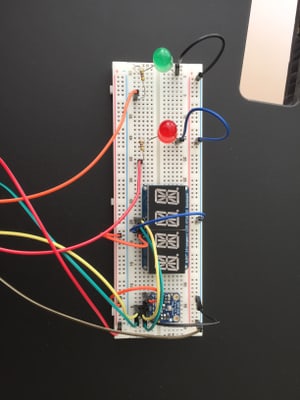
The first prototype I built is a small weather station. The temperature in the office was high and my idea was to measure the temperature of the room. Furthermore I wanted to light up a led if the temperature reaches a given threshold. A next step would be to switch on a fan for example .
To build the electronic circuit on the development breadboard, you’ll need a bit of electronic knowledge. This feels like becoming an electronic engineer, which is great! Reading a tutorial is great as a memory refresher. This one was very helpful to me.
One import thing to remember is Ohm’s Law U = RI , to know which resistance you have to put between the Raspberry PI and the LED. The resistance needs to respect the intensity of the LED that switches on automatically . It was also not easy to understand how the Peripheral I/O interface works at the beginning (where is the ground (-), power (+), functionality of the different pins, etc.). I printed the scheme here to have it next to me at all times.
General Purpose Input/Output (GPIO) provides a programmable interface to read the state of a binary input device or control the on/off state of a binary output device (such as an LED). The red LED was connected on pin BCM6 and the green LED was connected on pin BMC 5, for example. To get the temperature via the sensor and display it on the alphanumeric display, I used BCM2 and BMC3 (inter-integrated circuit bus).
The steps to create the Android Things app are the following:
- Create a Android project with a blank Activity in Android Studio and add the Android Things library and drivers in build.gradle
provided ‘com.google.android.things:androidthings:<version>'
implementation 'com.google.android.things.contrib:driver-bmx280:<version>'
implementation 'com.google.android.things.contrib:driver-ht16k33:<version>'- Add the following line in the AndroidManifest.xml under the application tag
<uses-library android:name="com.google.android.things"/>- In OnCreate of the MainActivity, register the peripherals
val service = PeripheralManagerService()
mSensorManager = getSystemService(Context.SENSOR_SERVICE) as SensorManager

//Temperature sensor
try {
    mEnvironmentalSensorDriver = Bmx280SensorDriver("I2C1")
    mSensorManager.registerDynamicSensorCallback(mDynamicSensorCallback)
    mEnvironmentalSensorDriver.registerTemperatureSensor()
    mEnvironmentalSensorDriver.registerPressureSensor()
    Log.d(TAG, "Initialized I2C BMP280")
} catch (e: IOException) {
    throw RuntimeException("Error initializing BMP280", e)
}

//Alphanumeric display
try {
    mDisplay = AlphanumericDisplay("I2C2")
    mDisplay.setEnabled(true)
    mDisplay.clear()
    Log.d(TAG, "Initialized I2C Display")
} catch (e: IOException) {
    Log.e(TAG, "Error initializing display", e)
    Log.d(TAG, "Display disabled")
    mDisplay = null
}

//Green LED
try {
    mGreenLedGpio = service.openGpio("BCM5")
    mGreenLedGpio.setDirection(Gpio.DIRECTION_OUT_INITIALLY_LOW)

} catch (e: IOException) {
    throw RuntimeException("Problem connecting to IO Port", e)
}

//Red LED
try {
    mRedLedGpio = service.openGpio("BCM6")
    mRedLedGpio.setDirection(Gpio.DIRECTION_OUT_INITIALLY_LOW)
} catch (e: IOException) {
    throw RuntimeException("Problem connecting to IO Port", e)
}- And finally register for sensor events:
private val mTemperatureListener = object : SensorEventListener {
    override fun onSensorChanged(event: SensorEvent) {

        mTempCount++
        if (mTempCount % 100 !== 0) {
            return
        }

        val temperature = Temperature(System.currentTimeMillis(), event.values[0])
        Log.i(FragmentActivity.TAG, "Temperature: " + temperature.getTemperature())

        mTemperatureTexView.setText(String.valueOf(temperature.getTemperature()))
        updateDisplay(temperature.getTemperature())

        try {
            if (temperature.getTemperature() >= TEMPERATURE_THRESHOLD) {
                mRedLedGpio.setValue(true)
                mGreenLedGpio.setValue(false)
            } else {
                mRedLedGpio.setValue(false)
                mGreenLedGpio.setValue(true)
            }
        } catch (e: IOException) {
            Log.e(TAG, "Error", e)
        }
    }

    override fun onAccuracyChanged(sensor: Sensor, accuracy: Int) {
        Log.d(TAG, "accuracy changed: $accuracy")
    }
}

private fun updateDisplay(value: Float) {
    if (mDisplay != null) {
        try {
            mDisplay.display(value)
        } catch (e: IOException) {
            Log.e(TAG, "Error setting display", e)
        }
    }
}
In the onSensorChanged callback for the temperature sensor, we filter events (otherwise we receive too many temperature changes) and display the value on the display with updateDisplay() . Once the value reached a certain threshold (TEMPERATURE_THRESHOLD), we switch the red or the green LED with setValue(true)/setValue(false).
And that’s pretty much it. Thanks to the Android framework and the implemented drivers it is very simple to communicate with the Raspberry PI using simple interfaces and without the need for low level programming.
Prototype 2: GPS tracker
In the next prototype, I wanted to test Android Things with a GPS antenna. If we come back to the Houston project, the idea would be to have an embedded device that is able to track the positions of the buses.
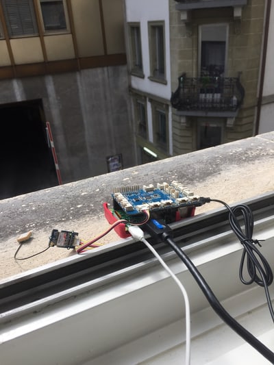
It was laborious to find out which GPS sensor to buy. There are many models so I decided to use the Grove GPS with GrovePi+. GrovePi+ offers a plug-and-play module for the Raspberry PI. You can connect Grove sensors without cables and breadboards.
It is possible to use the Grove Pi+ with Android Things, but I am not sure if it will work with all Grove sensors. I guess it depends on the connection interface you have (I2C, UART, …) and if there is a driver available for it. In my case, I needed a UART connection and it was enough to connect the Grove GPS to the RPISER port of the GrovePi+.
To create the Android Things app, the steps are the following:
- Create a Android project with a blank Activity in Android Studio and add the Android Things library and drivers in build.gradle
provided ‘com.google.android.things:androidthings:<version>'
implementation 'com.google.android.things.contrib:driver-gps:<version>'- Add the following line in the AndroidManifest.xml under the application tag
<uses-library android:name="com.google.android.things"/>- In onCreate of the MainActivity, register the GPS sensor
// Callback when SensorManager delivers temperature data.
val I2C_BUS = "I2C1"
val UART_BUS = "UART0"
val UART_BAUD = 9600
val ACCURACY = 2.5f // From GPS datasheet

...

mLocationManager = getSystemService(Context.LOCATION_SERVICE) as LocationManager

// We need permission to get location updates
if (checkSelfPermission(Manifest.permission.ACCESS_FINE_LOCATION) != PackageManager.PERMISSION_GRANTED) {
    // A problem occurred auto-granting the permission
    Log.e(TAG, "No ACCESS_FINE_LOCATION permission")
    return
}

try {
    // Register the GPS driver
    mGpsDriver = NmeaGpsDriver(this, UART_BUS, UART_BAUD, ACCURACY)
    mGpsDriver.register()

} catch (e: Exception) {
    Log.e(TAG, "Unable to open GPS UART", e)
}- Then, register the listener to receive location updates, just like for a standard Android code base.
 ...

// Register for location updates
mLocationManager.requestLocationUpdates(LocationManager.GPS_PROVIDER, 2, 0, mLocationListener)

...

val mLocationListener = object : LocationListener {
    override fun onLocationChanged(location: Location) {
        Log.v(TAG, "Location update: $location")
    }

    override fun onStatusChanged(provider: String, status: Int, extras: Bundle) {}
    override fun onProviderEnabled(provider: String) {}
    override fun onProviderDisabled(provider: String) {}
}
When you are running the app, you will see the current locations displayed in logcat. We can imagine to collect the locations in a Firebase Firestore database or display them on a map. We have seen, that it is very simple to build an Android Things prototype. As long as you have a bit of Android development experience and the correct driver and hardware setup, you’ll be okay.
Next steps
The goal of this innovation project was to experiment with the Android Things platform and discover if we could use it in our projects. It was great fun to build the electronic circuits and interact with the hardware via the Android framework. The setup is simple and the framework allows us to easily build a lot of amazing apps for IoT devices. You’ll find a lot of interesting use cases on the Web such as controlling you home switches remotely. Or even funnier examples like building an high five machine. Google insists on their website that the platform is not meant just for quick prototyping, but also for real products. Android Things is definitely a platform that was worth a try. The next step is to start integrating some of the Android code bases we have developed for Houston or other projects. We have a lot of ideas already!